Share with:
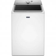
Whirlpool Calypso Washing Machine Repair Guide GVW9959
nu-ta-tion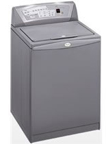
The spiral movement of the axis of a rotating body, such as the oscillation of a spinning top.
The Whirlpool Calypso Washing Machine was an early top loading energy saving washer produced in 2000-2001. It is a good washer design for the most part but is notorious for pump problems. This washer style is slightly more complicated than most top loading washers. It’s mechanical functions are controlled by two control boards, the Machine Controller Board and the Motor Control Board, as well as several sensing devices. This Calypso washer repair guide will cover the components used in the calypso washing machine, troubleshooting common calypso washing machine problems, calypso washing machine diagnostic modes, Calypso error codes, and information to help with testing individual calypso components.
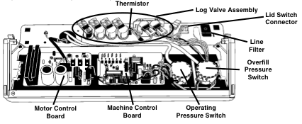
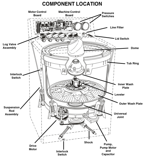
Calypso Washing Machine Parts
CONSOLE SWITCH PANEL, MACHINE CONTROLLER BOARD, MOTOR CONTROL BOARD, LID SWITCH, DRIVE MOTOR, LEVELER, UNIVERSAL JOINT, DRIVE SYSTEM, PRESSURE SWITCHES, LOG VALVE ASSEMBLY, WATER PUMP
CALYPSO CONSOLE SWITCH PANEL
(part# 8563810 Pewter)
(part# 8563809 Pearl)
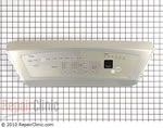
The Whirlpool Calypso washing machine uses a panel of switches also called a membrane to receive and relay the user’s commands to the machine controller board for further processing. When a button is pressed temporary contact is made with in the membrane allowing the machine controller board to log the command and initiate the appropriate cycle and wash options.
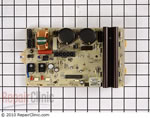
CALYPSO MACHINE CONTROLLER BOARD
(part# 8571359)
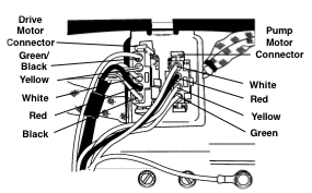
The Machine Controller interprets your commands from the key switch pads tooperate the cycle selected. The Machine Controller interfaces with the Motor Controller through the P4 and P2 connections to operate the Drive motor and Pump motor through their various functions during the cycle. The Machine Controller also directly operates the water fill and dispenser solenoids, interprets the thermistor readings, lid switch condition, as well as the position of the contacts in the Operating and Flood Pressure switches.
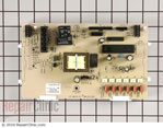
CALYPSO MOTOR CONTROLLER BOARD
(part# 8541034)
The Motor Controller receives commands from the Machine Controller to operate the Drive Motor at the desired speed and direction at various times in the cycle. It does so by applying varying voltages and frequencies to the Drive Motor. The Motor Controller also operates the Pump Motor direction to either recirculate or drain water.
CALYPSO LID SWITCH
(part# 8272124)
The Lid switch is used to sense if the lid is closed and it is safe to proceed with the washing machine’s nutation and spin functions. The Calypso washer is equipped with a peekaboo mode that allows the washer to continue nutation for 5 seconds after the lid has been opened. After the lid is closed the start button must be pressed to continue the wash cycle.
CALYPSO DRIVE MOTOR
(part# 285917)
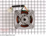
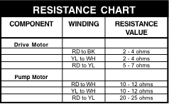
This washer uses a reversible, variable speed (Single Phase Induction Motor) as its main drive motor. Motor speed varies from 350 RPM to 4500 RPM. The ½ horsepower motor draws five to seven amps, in normal use. It uses a voltage output from the motor controller and operates at variable AC voltages and frequencies. The Motor Controller provides a variable frequency signal to the motor, which provides the various speeds to nutate and spin. Checking voltages to the drive motor should not be attempted.
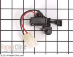
CALYPSO WATER PUMP
(part# 285990)
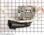
The pump is directly driven by a separate reversible 120 VAC 60 Hz motor. By being reversible, the motor provides for two separate operations of the washer.
Other Calypso Washing Machine Links:
Calypso Washing Machine Diagnostics Mode Help
Calypso Washing Machine Problem Troubleshooting
CALYPSO UNIVERSAL JOINT
(Kit Part# 285927)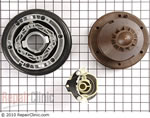
During Nutation, the Wash Plate is tipped at a 35 degree angle and must be free to undulate to move the clothing properly. The Wash Plate is attached to a Universal Joint that allows the Plate that freedom of movement. The Universal Joint is attached to the basket drive block by a spanner nut and is sealed top and bottom by a boot and various seals to keep water from damaging its pivoting parts. The boot is attached to the bottom of the U-Joint and prevents water from getting to the U-Joint from underneath. Attached to the basket drive hub is an O-ring that forms a seal between the U-Joint boot and the basket drive hub. The top of the U-Joint is sealed by six, (6), grommets and a gasket that is attached to the underside of the inner wash plate. The six grommets, wash plate gasket and/or O-ring MUST be replaced whenever their sealing surface(s) have been disturbed. The Seal Kit is Part #285842.
CALYPSO LEVELER (Part# 285910)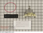
The leveler tilts the nutate or outer wash plate from a level to a 35 degree tilted position. The leveler is driven by the nutate shaft which replaces the traditional agitator shaft. A shifting mechanism on the underside of the leveler moves it from a perpendicular alignment in the spin mode to the 35 degree tilt required for nutation. In the spin mode, the top of the leveler is positioned to be in line with the nutate shaft. This levels the outer wash plate so that the spin basket spins without an out of balance condition that would be caused by a tilted wash plate. The leveler shift mechanism is moved from nutate to spin by the nutate shaft direction and an interference with the inner wash plate.
CALYPSO DRIVE SYSTEM
The Drive Motor operates the nutate and spin functions by reversing direction. The Drive Motor is linked to the drive mechanisms by a stretch belt (part# 8562613). The belt transfers the motion of the Drive Motor to a Drive Pulley. The Drive Pulley has a splined hub, into which the Nutate Shaft is inserted and is in motion in whichever direction the Drive Pulley is turning. The Drive Pulley, Drive Motor and Drive Belt all turn in a clock-wise direction, as viewed from underneath when the system is Nutating. The Drive Motor reverses direction for Spin and causes the Drive Pulley to turn in a counterclockwise direction, as viewed from underneath. When turning in this direction, an actuating bump in the hub of the Drive Pulley will contact the Brake Release pawl on the Spin Tube/Brake assembly. This releases the brakes and allows the basket to spin.
CALYPSO PRESSURE SWITCHES
Operating pressure switch “OPR” (Part# W10311359)
Recalculation pressure switch “FLD” (Part# 8054767)
The washer uses two pressure switches to control the amount of water entering the tub and to protect against an overfill condition. The operating pressure switch, marked OPR, controls the amount of water that enters the tub during normal wash and rinse functions. This switch operates in the same manner as similar pressure switches through a pressure switch tube, diaphragm and switch. The switch contact is normally closed and will open on pressure rise. The overfill pressure switch, marked FLD, is used to guard against failure of the operating pressure switch or an overfill condition caused by the consumer adding water to the basket. The overfill pressure switch operates in the same manner as the operating pressure switch, except it’s trip setting is slightly higher than the operating pressure switch. The switch contact is normally closed and will open on pressure rise. These pressure switches are NOT interchangeable. If an overfill condition is detected, the overfill switch will signal the electronic control which  causes it to discontinue the current cycle. “FL” will flash on the control panel display and the beeper will repeat a warning every 10 seconds. The pump is cycled in drain mode for a half minute on, half minute off until the overfill switch is reset or power is disconnected from the washer. If the flood switch does reset, the washer will remain in standby mode with “FL” displayed. It will not automatically restart the cycle.
CALYPSO LOG VALVE ASSEMBLY (Part# 9724754)
The log valve assembly consists of an inlet valve with hot and cold water valves and solenoids for incoming water supply and four (4) outlet valves for the water to exit the valve body. The outlets drive the dispensers under the washer top and allow for fresh water fill. Also included in the log valve assembly, is the thermistor which is used to monitor incoming water temperature.
The table below shows what resistance level the thermistor should have at a given temperature. It’s best to let things cool down and use room temperature as a known value.
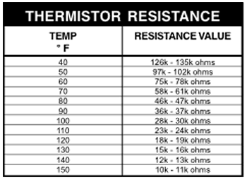
Click Here to learn how to use a multimeter for measuring resistance values
CALYPSO RECIRCULATION and DRAIN
CALYPSO WATER PUMP (Part# 285990)
The pump is directly driven by a separate reversible 120 VAC 60 Hz motor. By being reversible, the motor provides for two separate operations of the washer.
CALYPSO OUTER TUB SUMP
The Outer Tub sump plays a role in the drain and water recirculation function The sump area includes two check balls that direct water flow when the water pump operates in the drain and recirc direction. When water is present in the tub, the check balls will float in the proximity of the recirculation and drain sump ports. Water weight or water pressure applied to the ball(s) will cause them to drop away from their respective port or seal off the port.
CALYPSO RECIRCULATION
During the Recirculation Mode, the pump motor turns counter-clockwise (as viewed from underneath the washer). This causes the water pump to draw water from the tub through the drain sump port, forcing the recirculation check ball to seal the recirculation sump port and force water through the recirculation tube outlet. Water is recirculated back into the tub onto the load.
CALYPSO DRAIN
During the Drain Mode, the pump motor turns clockwise (as viewed from underneath the washer). This causes the water pump to draw the water from the tub through the recirculation port, forcing the drain check ball to seal the drain sump port and force the water through the drain hose.
Share with:
Pages: 1 2