Understanding Wire Diagrams
That's Not Trash, It's Your Wire Diagram!
Wire diagrams can be intimidating at first, but with a basic understanding of the symbols and language used, they become as valuable and as easy-to-use as any tool in your toolbox. Wire diagrams are an important part of accurate appliance troubleshooting and repair!
Circuit Elements | Series Circuit | Parallel Circuit | Symbols | Electrical ComponentsWire Colors
Elements of a circuit
Circuit Video
1. Power Source
A circuit must have a power source such as electricity supplied by a wall socket, battery, or generator.
2. Conductors
Conductors are usually copper or aluminum wire, and in some cases it can even be the frame on which the components are mounted.
3.Load
The load is the components that do all the work, such as a washer motor, heating element, or light bulb.
4. Control
Controls are devices that control the flow of electricity to the loads. A control is usually some sort of switch that is operated by the user of the appliance, or operated by the appliance itself.
Circuit Types
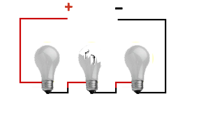
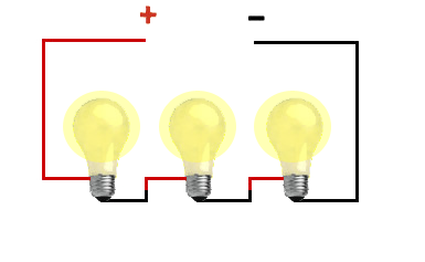
Series Circuit
The current that flows in a series circuit will pass through every component in the circuit. If any component within the circuit is "open" or "blown," current will not be able to flow through that circuit.
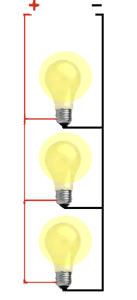
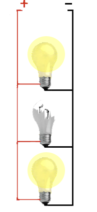 Parallel Circuit
In a parallel circuit, two or more components are connected in parallel; they have the same potential voltage across their ends, and they also have identical polarities. The same voltage is applicable to all circuit components connected in parallel. In a parallel circuit, power can flow around an "open" contact and continue to supply power to other components in the circuit (image on right).
Wiring diagrams are like road maps showing you the direction of current flow. Just as with a road map, you will need to know a few basic symbols so you can figure out where you're going.
Below is a wiring diagram / schematic of a direct-drive washing machine. Click on the highlighted primary components for a more complete description of what they are and how they work.
Contact:
Wires are connected and electricity is able to flow through this connection.
No Contact:
Many times appliance wire diagrams can become complex. This symbol means that the wires are not connected and no electricity can flow directly 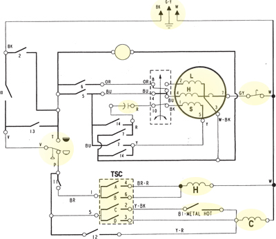 through this point.
Ground or Earth Connection:


This connection is very important. It's usually made with a bare wire attached to the cabinet of an appliance, which is in turn connected to earth within the service panel of your home through a "grounded" plug. This connection serves a safety to protect against electrocution in the case of a short.
All electrical circuits must have a load. Loads have many forms and purposes. An electric dryer or stove uses a resistor called a heating element to create heat. A coil is used to automatically open and close valves with a magnetic field. A refrigerator
uses fan motors to circulate air.
A list of component descriptions and diagram symbols can be found on the "electrical components" page.
Wire Colors
Wire diagrams use wire color codes to identify the color of wire being used to connect different electrical components within the circuit. Some wire colors are specific to the wire's use such as black, white, red, and green, while others are used for component connection and change function from one circuit to another. Most wire diagrams will have a legend or key just like a road map explaining wire color codes or any other special information needed to read the diagram. Below is a list of color codes commonly used in wire diagrams to portray wire color and their purposes.
Wire color |
Wire Function |
WH=White |
Neutral wire carrying current at zero voltage |
BK=Black |
Hot wire carrying current at full voltage |
RD=Red |
Hot wire carrying current at full voltage |
WH/BL=White with black markings |
Hot wire carrying current at full voltage |
GR=Green |
Grounding pathway |
G-Y=Green with yellow markings |
Grounding pathway |
Bare copper |
Grounding pathway |
YL=yellow |
Multifunctional |
BU=Blue |
Multifunctional |
GR=gray |
Multifunctional |
YL/BR=yellow with brown markings |
Multifunctional |
others (use diagram key) |
Multifunctional |
Back to Top
Want More?
Basic Electricity PDF2
HOW TO READ:
• WIRING DIAGRAM SYMBOLS
• TERMINAL CODES
• WIRING DIAGRAMS
Basic Electricity PDF 3
HOW TO READ:
• TIMER SEQUENCE CHARTS
• WIRING DIAGRAMS
