Share with:
How Gas Stoves Ranges & Ovens Work
Cook’n With Gas
Gas Supply | Temperature Wave | Pilot ignition Ovens | Electronic ignition Ovens | Direct Spark Ovens | Pilot Ignition Burners | Electronic Ignition Burners
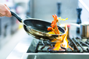 Cooking may have become easier than trying to start a fire with two sticks. But when your burners won’t light or the oven doesn’t want to heat up what do you do? In this section I will outline the mechanical and electrical components used within your stove top and oven to create and maintain the correct amount of heat, necessary to impress your friends with a five-course meal. I will also describe some of the problems that can turn your culinary masterpiece into a hungry man microwave dinner.
Cooking appliances come in two main flavors, Electric and Gas. In this section I will primarily be discussing gas-cooking appliances. For a closer look at electric ovens and stoves check out “Cook’n With Current.”
Gas Supply
Gas Stoves usually come ready for natural gas, but most models can be modified with a few extra fittings and minor adjustments. Gas enters the stove through a pressure regulator. This component does just what you would expect it to do; it regulates gas pressure to the rest of the appliance. Your home or propane tank also has a pressure regulator but this secondary appliance regulator acts as a guarantee that gas is under the correct amount of pressure for proper appliance operation. Pressure regulators need to be installed in the correct direction to allow gas to pass through and will usually have an arrow marked on the regulator showing the proper direction of gas flow. Often the regulator is integrated into the oven’s control valve.
Temperature Wave
Your oven is constantly cycling on and off automatically to maintain a temperature range close to what you have set at the oven thermostat. Some
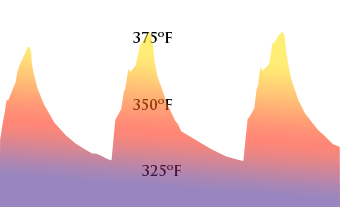 ovens have more accurate thermostats than others. The oven’s ignition system should automatically open a valve releasing gas, which is then ignited and begins heating the oven cavity. Once the oven has slightly passed the target temperature the thermostat closes the valve allowing the oven to cool. When the oven as dropped to the low side of the temperature range selected the thermostat re-energizes the ignition system for more heat to be generated. In this way a wave of temperature is produced.
Temperature Problems can occur when the thermostat fails to detect the correct temperature within the oven cavity, causing an oven that is ether to hot or to cold, or the ignition system used is slow to open the oven’s valve causing lower than normal temperatures.
There are two main methods of igniting the gas, pilot ignition, which is a small continual flame, and electronic ignition, which uses a momentary arc or heating element as a heat source capable of initiating gas combustion. Obviously appliance manufacturers are concerned with safety when releasing flammable gas into your home, so there are a few things that need to happen with both styles of ignition before the oven valve lets the gas fly.
Pilot Ignition Ovens
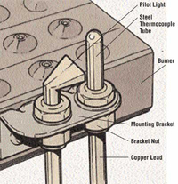 Pilot ignition ovens are very effective at safely opening an automatic gas valve at the proper time, as well as cycling the oven burner off and on to maintain an optimum temperature; however, they are rarely used anymore because of the constant gas or flame source, which raises safety concerns in sue happy world. The pilot ignition oven uses a device called a thermocouple using the thermoelectric effect, which converts heat into electricity causing the valve to open and release gas.
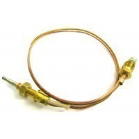
Common Problems with this system can occur when the thermocouple fails to produce the electricity required to open the valve. But more often the pilot flame used to create the heat necessary for the thermocouple to do its job goes out. Some stoves require that you press the oven temperature knob in while relighting the oven’s pilot flame.
Electronic Ignition Ovens
Glow Bar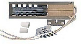
Electronic ignition ovens use a component called an igniter, which is usually a “glow bar” that gets red hot, when supplied with electrical current. As the electricity passes through this special material heat is created and the molecules within the igniter expand slightly, allowing more electrical current to  flow through the igniter to the oven’s automatic gas valve. In this way the valve will not open unless the igniter is hot enough to instantly light the gas that is released.
Common problems with the glow bar ignition method usually come in the form of the oven temperatures being too cool, or things not being completely cooked. These symptoms could be a thermostat or sensor problem, but most often the igniter is not getting hot enough to open the valve. This causes the burner to take longer than normal to open and so the oven temperature wave dips toward the cool end. After a while of tolerating cool oven temperatures the oven may stop heating all together. The glow bar should release and ignite gas in seven to twenty seconds after the oven is turned on. Yes the igniter can glow and still be defective!
Note: a small click sound can usually be observed on ovens with a digital electronic control. This sound is the internal relay switch closing, energizing the ignition system, starting your seven to twenty second count down.
Direct Spark
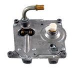 Direct spark ignition is a slightly more complicated system; however, the benefits are faster burner ignition and more accurate oven temperatures. The direct spark oven ignition method uses “DSI” control to generate the current necessary to create the arc needed for the burner to light. An igniter similar to the spark plug in your car is mounted next to the burner and clicks as it produces an arc to light the gas being released. This system also uses a slightly different gas distribution valve. This valve has two solenoids inside of it to release gas when needed as well as a gas shut off switch. These solenoids should measure 216Ω of resistance (always check both solenoids if either one is bad neither will operate.) and should open when supplied 8-18 DCV
Common Problems
with this system can be caused by the igniter itself failing to generate the spark required, the “DSI” control not sending the proper amount of electricity to a particular component, the solenoids inside the gas distribution valve not opening, or the gas shut off switch accidentally being closed by some object in the lower drawer. View The DSI Service Manual manual for information on troubleshooting the direct spark ignition system.
Surface burners
Pilot Ignition
 Pilot ignition surface burners work in much the same way but a thermocouple is not needed because the valve is not automatic, the user would manually open the burner valve at the front of the stove releasing the correct amount of gas for the desired amount of heat. A small amount of gas will then flow through tiny holes in the side of the burner head and down a connecting tube to the burner’s pilot flame. There are usually two pilot flames, one for the right front and rear burners and one for the left front and rear burners.
Common Problems with this system can occur when a pilot flame goes out or the small holes that allow gas to flow into the ignition tube become clogged or blocked. If the pilot light is on but the burners will not light quickly try cleaning these holes out with a needle or pin. The pilot flame size can usually be adjusted up or down with a flat head screw control on top of the small gas tubing that supplies gas to the pilot lights. The pilot flame should be just large enough to stay on, but not so large that the stove top becomes extremely hot.
Electronic Ignition
Electronic ignition surface burners are the new standard. This method of burner 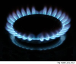 ignition uses a spark module to generate the current necessary to create the arc needed for the burner to light. The spark module is located in deferent locations depending on your stove model; it can be easily located by following the igniter wires back to their source, or using the model search box in the left side page menu to find an exploded drawing for your model.
  The spark module is supplied 120 Volts AC through a switch that is mounted behind the burner control knob, when the knob is turned the switch rotates and closes, allowing electric current to flow through to the spark module. The spark module then supplies a high voltage repeating pulse to the igniter.
Common Problems
with this system can occur when the spark module fails to send the proper amount of current required for the igniter to produce a spark, the igniter breaks or arc contacts become dirty or misaligned, the burner switch wont allow electricity to flow through to the spark module, or a connecting wire breaks fails to carry the electricity needed to component in the stoves ignition circuit.
Share with: